Interaction
UART: Structured Asynchronous Communication
How two independent systems learned to agree on time.
UARTSerial ProtocolsAsynchronousBaud RateEmbedded Systems
1. From Raw Voltage to Structured Language
At its absolute physical foundation, a General Purpose Input/Output (GPIO) line is a simple copper trace holding a voltage. It can be pulled high, or it can be driven low. In isolation, a voltage transition is a binary event—a simple statement that something has changed. But if two independent processors are to exchange thoughts, a raw voltage transition is not enough. Without structure, a change in state is indistinguishable from electrical noise, and there is no way to represent a sequence of letters, numbers, or commands.
Universal Asynchronous Receiver-Transmitter (UART) is the architectural answer to this limitation. It is the bridge that transforms a simple, volatile voltage line into a channel for structured information. It does this not by adding more wires or introducing a complex shared clock, but by establishing a strict contract: an agreement on how time and voltage translate into a digital language.
By eliminating the physical clock line, UART minimizes physical pin count to a bare minimum: Transmit (TX), Receive (RX), and a shared Ground reference. But this simplicity at the physical layer moves the engineering burden entirely into the domain of timing agreements. The devices must agree on a set of rules—a communication contract—that allows them to reconstruct structured data from the transient rise and fall of voltages.
2. Anatomy of the UART Frame
To transmit structured data asynchronous to any clock, UART packages bits into small, predictable containers called Frames. Each frame is a sequential series of voltage levels representing synchronization markers, the payload, and validation data. Understanding the frame is to understand the engineering motivation behind each transition:
• Idle State: When no data is being sent, the line remains at a constant High voltage level (logical 1). Keeping the line high serves two purposes: it makes the link noise-resistant during quiet periods, and it ensures that a transition to Low is instantly detectable as a deliberate communication event rather than passive interference.
• Start Bit: The transmission starts with a sharp, forced transition from High to Low (logical 0) for exactly one bit period. This falling edge is the receiver's alarm clock. The moment it occurs, the receiver's hardware wakes up, resets its internal timing counters, and aligns its sampling logic to the start of the payload.
• Data Bits: Following the start bit, the payload—typically 8 bits—is serialized and driven onto the line, Least Significant Bit (LSB) first. Sending LSB first simplifies the design of shift registers in silicon, as the lowest bit corresponds directly to the first shift out.
• Parity Bit: An optional mathematical helper used for error detection. The transmitter counts the number of logical 1s in the data and sets the parity bit to ensure the total count is either Even or Odd. If a stray electromagnetic spike flips a voltage on the wire, the receiver's computed parity will not match the received parity bit, signaling a transmission failure.
• Stop Bit(s): To conclude the frame, the transmitter drives the line back to a High state (logical 1) for one or two bit periods. This stop bit ensures the line is held at High, creating a clean boundary and guaranteeing that the next frame can start with a visible High-to-Low transition.
The diagram below represents the exact structure of a single UART frame as it progresses over the physical line from left to right:
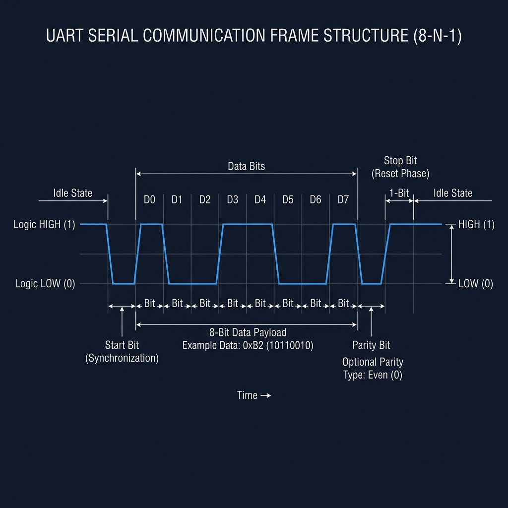
UART Frame Schematic Layout
3. The Synchronous Expectation
Asynchronous communication is fundamentally a contract of expectations. Since the receiver has no shared clock line to coordinate when to sample, it must rely entirely on its local oscillator. The receiver listens for the falling edge of the Start Bit, waits for 1.5 bit-times to sample the first data bit at its exact physical center, and then samples every subsequent bit at 1-bit intervals.
This mechanism is highly sensitive to clock differences. If the transmitter sends data at 9600 bps (104.16 µs per bit) but the receiver's clock runs slightly slower, the receiver's sampling points will accumulate an error. By the time it reaches the 8th data bit or the stop bit, the phase drift can be so large that it samples a transition edge or an adjacent bit. This is why UART frames are kept short—by resetting the timing alignment on every single frame's Start Bit, the accumulated phase error is reset to zero before it can corrupt the data.
UART does not synchronize processors. It synchronizes expectations. A microcontroller running at 120 MHz can speak perfectly to a server running at 2 GHz, because they have agreed to slice time and voltage in the exact same way.
4. Interactive: Build a UART Conversation
Use the interactive conversation builder below to explore how letters are encoded into ASCII, packed into serial UART frames, and transmitted as electrical voltages. Toggle the advanced mode to simulate mismatched configurations and observe how timing errors corrupt the signal.
The Baseline Contract
In the physical layer, there is only voltage over time. It is the shared protocol agreement that turns this electricity into human language.
UART remains the ultimate baseline interface because it demonstrates that system coordination is not a matter of speed, but of agreement.
Time is the invisible wire in asynchronous communication. When we agree on time, we only need a single wire for the conversation.
Current Exploration
UART: Structured Asynchronous Communication