Interaction
CAN: The Language of Many Voices
How differential signaling and destructive-free arbitration solved the noise and coordination challenges of multi-master buses.
CAN BusDifferential SignalingArbitrationMessage RAMHardware Safety
1. The Single-Ended Voltage Failure
In our earlier explorations, we watched systems learn to speak. UART established a simple contract between two nodes. SPI shared a clock to unlock extreme speeds. I2C shared clock and data lines using open-drain logic and addressing, allowing dozens of chips to coexist on a single two-wire bus.
Yet, all three protocols share a fatal vulnerability: they are single-ended. They measure logic states by comparing the voltage of a signal line against a common reference: ground. If a signal line is at 3.3V relative to ground, it is a 1; if it is at 0V, it is a 0.
This architecture works beautifully on a clean PCB. But transport these wires onto a factory floor, an elevator shaft, or a car engine bay, and the physics changes. High-current electric motors, ignition systems, and magnetic fields induce voltage spikes in nearby wires. If electromagnetic interference (EMI) induces a +1.5V spike on the signal line, a 0V logic level is suddenly misread as 1.5V (which can be interpreted as a logic 1). If ground offsets occur between nodes due to long cables, the common ground reference drifts, and nodes lose the ability to interpret each other's voltages. In a noisy world, single-ended coordination collapses.
2. Differential Signaling: Noise Cancellation through Subtraction
In 1983, Bosch engineers designing automotive electronics realized that they could not eliminate electrical noise; they had to learn to ignore it. The result was the Controller Area Network (CAN) bus.
To defeat noise, CAN discards the single-ended model in favor of differential signaling. Instead of one signal line and a ground reference, CAN uses two dedicated lines twisted together: CAN High (CANH) and CAN Low (CANL).
When a noise spike hits the twisted-pair cable, the electromagnetic fields affect both wires equally. If a motor induces a +1.0V spike, it shifts both CANH and CANL up by exactly 1.0V. The receiving node does not measure each wire against ground; instead, it measures the voltage difference between them (Vdiff = V_CANH - V_CANL). Because the noise spike is added to both wires, subtraction cancels it out completely:
(V_CANH + V_noise) - (V_CANL + V_noise) = V_CANH - V_CANL
This simple mathematical physics makes CAN almost completely immune to common-mode noise, allowing it to communicate reliably over hundreds of meters in the most hostile environments.
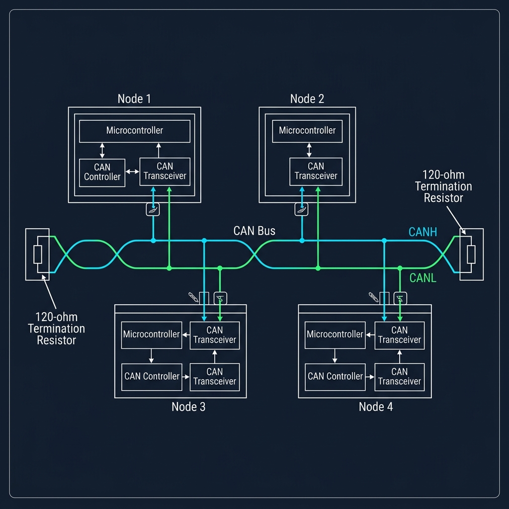
CAN Network Topology showing CANH and CANL twisted pair with nodes and transceivers
3. Dominant and Recessive: The Wired-AND Evolution
How do we transmit data on this differential bus? CAN takes a page from I2C's open-drain playbook but elevates it to a differential drive.
In I2C, a node either actively pulls the bus LOW or releases it to float HIGH via pull-up resistors. CAN implements a similar philosophy using dominant and recessive states:
1. Recessive State (Logic 1): The transmitter drivers are turned off. Both CANH and CANL float to a nominal 2.5V, driven by terminating resistors. The differential voltage is Vdiff = 2.5V - 2.5V = 0.0V.
2. Dominant State (Logic 0): The transmitter actively drives the lines apart. CANH is driven high to 3.5V, and CANL is driven low to 1.5V. The differential voltage is Vdiff = 3.5V - 1.5V = 2.0V.
Because the dominant state actively drives the lines while the recessive state passively lets them float, a dominant bit (0) will always override a recessive bit (1). If one node attempts to write a recessive 1, but another node writes a dominant 0, the bus resolves to a dominant 0. This dominant/recessive physics forms the basis of CAN's collision-free, multi-master arbitration.
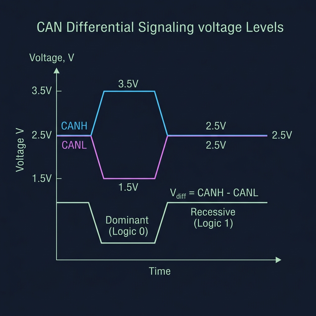
Differential Voltage Levels: Dominant vs Recessive on CANH and CANL
4. The Physics of the 120 Ohm Terminator
Look at any CAN network, and you will find a 120 Ohm resistor at each extreme end of the bus, bridging CANH and CANL. These are not simple pull-up resistors; they are transmission line terminators.
At high speeds, electrical signals behave like waves in water. When a voltage transition travels down a wire, it carries electrical energy. If it hits the open end of a cable, it encounters a boundary mismatch: the energy has nowhere to go, so it reflects back down the wire in the opposite direction. These reflected waves bounce back and forth, colliding with new incoming bits and corrupting the waveform.
To prevent signal reflections, we must match the cable's characteristic impedance. A standard twisted-pair cable has a characteristic impedance of 120 Ohms. Placing 120 Ohm resistors at both ends acts as an electrical sink: the incoming wave's energy is completely absorbed and converted to heat, preventing any reflections and maintaining pristine signal integrity.
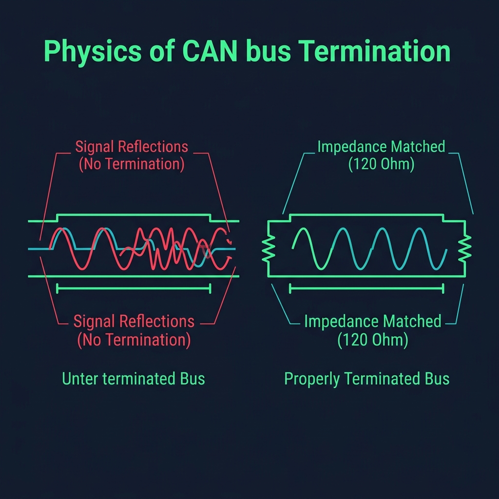
CAN Bus Termination: Impedance Matching vs Signal Reflections
5. Bit Arbitration: The Conversation of Dominance
In SPI, a master dictates timing and selection. In I2C, a master addresses slaves. But CAN is a peer-to-peer network: there are no masters or slaves, only nodes. Any node can transmit whenever the bus is idle.
What happens when three nodes start transmitting at the exact same microsecond? In Ethernet, this causes a collision; the nodes stop, wait a random interval, and try again, wasting bandwidth. CAN solves this using bitwise arbitration.
Every CAN frame begins with an Identifier (ID), which serves two purposes: it defines the priority of the message and labels the data content. When multiple nodes start transmitting, they write their ID bits onto the bus one bit at a time while simultaneously reading the state of the bus.
If Node A writes a recessive 1, but Node B writes a dominant 0, the bus becomes dominant. When Node A reads the bus, it notices the mismatch: it wrote a 1, but it sees a 0. Knowing that another node with a higher priority (a lower numerical ID) is transmitting, Node A immediately falls silent, dropping out of arbitration. Node B continues uninterrupted. This arbitration is completely non-destructive: the winning message is delivered without a single bit of corruption.
6. Frame Architectures: CAN 2.0A vs CAN 2.0B
As networks grew, the original 11-bit identifier space (CAN 2.0A) proved too small for complex systems. To expand this, engineers introduced the Extended CAN frame (CAN 2.0B).
1. Standard Frame (CAN 2.0A): Uses an 11-bit identifier, allowing up to 2,048 unique message priorities. It is the core format for basic automotive and industrial networks.
2. Extended Frame (CAN 2.0B): Uses a 29-bit identifier, expanding the space to over 536 million unique priorities. This is achieved by splitting the ID into an 11-bit Base ID and an 18-bit Extension ID, separated by the IDE (Identifier Extension) and SRR (Substitute Remote Request) bits. If a standard and an extended frame with the same base ID compete, the standard frame wins arbitration because its IDE bit is dominant (logic 0), whereas the extended frame's IDE bit is recessive (logic 1).
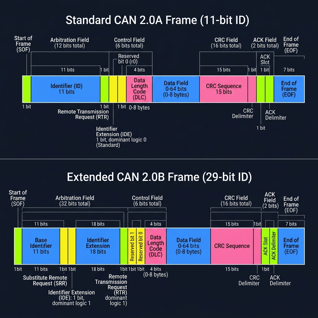
CAN 2.0A Standard vs CAN 2.0B Extended Frame Layouts
7. The Safety Layer: Stuffing, CRC, and ACK
Because CAN has no shared clock line (like SPI or I2C), nodes must synchronize their clocks using the transitions (edges) of the incoming data bits. If a message contains a long sequence of identical bits—for example, a data payload of 0x00 (all 0s)—the line remains flat, and the nodes' clocks drift out of sync.
To maintain synchronization, CAN uses bit stuffing. If the controller detects five consecutive bits of the same polarity, it automatically inserts an opposite 'stuff bit' into the stream. The receiving controller detects these stuff bits and strips them out before delivering the data, ensuring the receiver's phase-locked loop (PLL) stays locked to the transmitter.
Additionally, CAN includes robust integrity checks. The transmitter appends a 15-bit Cyclic Redundancy Check (CRC) checksum. After the CRC comes the Acknowledge (ACK) slot. During the ACK bit, the transmitter writes a recessive 1. Every receiver that successfully validated the frame overrides this slot by writing a dominant 0. If the transmitter reads a 0 in the ACK slot, it knows at least one node received the frame correctly. If it reads a 1, it assumes a transmission error and retransmits the message.
8. Message RAM: The Hidden Geography of Firmware
In our earlier journey through The Hidden Geography of Firmware, we saw that SRAM is not a uniform block of memory. It is divided into distinct regions, and modern microcontrollers often allocate specific, hardware-accessible partitions for peripheral data. CAN controllers are a prime example.
In high-performance microcontrollers (such as the STM32H7 or microcontrollers containing Bosch's M_CAN IP), CAN frames are not handled directly in general-purpose CPU registers. Instead, they are written to and read from a dedicated region of memory called Message RAM.
This Message RAM contains the configuration for receive and transmit buffers, filters, and FIFO queues. Because the CAN peripheral's hardware controller reads and writes to this RAM region directly via DMA (Direct Memory Access), the firmware developer must carefully define the start address and offsets of these buffers in linker scripts or configuration registers. A misalignment of a single word in the Message RAM boundary causes the CAN hardware to generate a bus fault or corrupt frame routing. To write robust CAN drivers, you must understand the exact physical layout of your microcontroller's memory map.
The Cooperative Network
CAN represents the pinnacle of cooperative embedded networking. By replacing central master control with distributed, non-destructive bit arbitration and robust differential physics, it creates a system where nodes can converse reliably in the presence of noise that would disable any other protocol.
It reminds us that robust communication does not require silence from others; it requires a physical layer that allows voices to merge and resolve their differences without corruption.
When machines speak in many voices, harmony is not achieved by force, but by a physical agreement on who steps aside.
Current Exploration
CAN: The Language of Many Voices