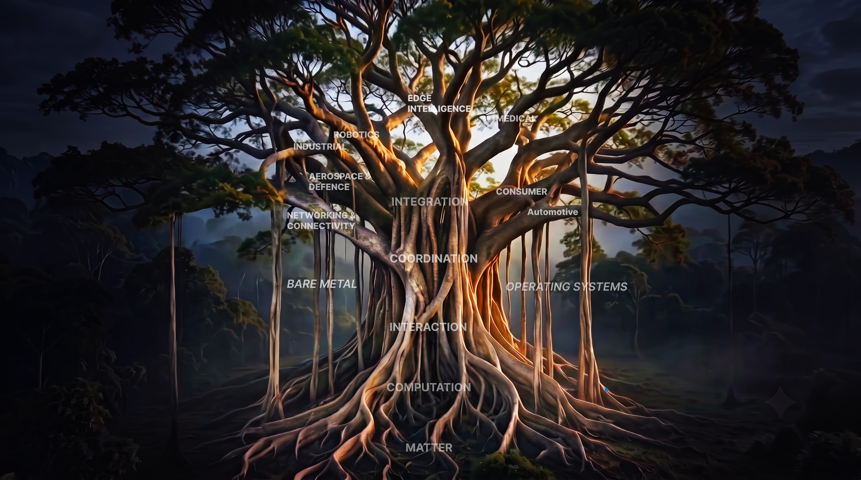
PrajnaEdge is not navigated like a conventional website. Knowledge is represented through paths, structures, and transitions.
Matter
NodesClick a node name to enter that concept and continue along the awakened path.
Exploration ListBegin your journey by selecting an exploration from the exploration list.
ExplorationAn Exploration is the main step-by-step learning experience containing theory, visuals, and interactive elements.
SetuA Setu connects related concepts that can be explored independently from the main sequence.
VortexA Vortex opens a path toward another knowledge area, foundation, or future domain.
For the best experience, open PrajnaEdge on a desktop or laptop screen.
PrajnaEdge
An interactive engineering platform where complex concepts become experiences—through visual explorations, simulations, and practical understanding.
Embedded Systems Tree
On the Horizon
PravahaPath
Something new is taking shape.
Articles & Write-ups
Exploring how systems evolve from hardware to integration.
Sort:
Edge AI Demonstrations
Deploying neural networks and intelligent decision loops on raw silicon targets.
Sort:
Bare Metal
Before main()
The hidden choreography that prepares raw silicon for your first line of C.
Bare MetalBootloaderLinker ScriptReset VectorC Runtime
1. The Myth of the Beginning
To the software engineer, the universe of an application begins with a familiar and comforting signature:
int main(void) { ... }
It is the genesis of our code, the entry point for our debuggers, and the boundary line where high-level state starts its execution. We write our routines under the quiet assumption that the machine starts here, waiting as a clean, blank slate for our first instruction to call it to action.
But this starting line is an artificial boundary. The CPU did not begin at main(), nor does it understand the high-level syntax of a C function. Long before the first line of your main loop runs, the microcontroller has already completed a massive journey. It has left its analog reset state, evaluated physical boot flags, routed through vendor ROMs, set up stack space, copied segments across physical memories, and configured clock frequencies. Before C can exist, the machine must build the world C assumes already exists.
main() is not the beginning of computation. It is the final handoff from hardware reality to software abstraction.
2. Hardware Wakes: The Reset State
When power climbs the capacitive rails of a microcontroller, or the physical reset line is toggled, digital logic does not instantly begin computing. The core starts in an architecture-defined reset state where pipelines are flushed, registers are set to default values, and interrupts are globally disabled.
We have seen this moment before. In The First Instruction, we traced how analog supervisors release the CPU to fetch its initial Stack Pointer and Reset Vector. Here, we step back to examine the branching boot systems that govern this transition.
How the processor finds its first executable byte depends on its silicon architecture. There is no single universal embedded boot sequence. While a simple microcontroller might immediately point its Program Counter (PC) to a fixed vector table in Flash, a complex SoC or application processor might boot into an immutable on-chip Boot ROM, check boot pins, or load custom bootloader binaries from external media.
3. The Boot Decision Tree
Rather than following one mandatory sequence, microcontrollers and SoCs branch into different boot configurations depending on vendor design, boot configurations, and product architecture. A simple MCU boots directly into application code, while a production-grade secure system routes through multiple stages of software validation.
THE JOURNEY TO MAIN(): DEVICE-DEPENDENT BOOT PATHS
Optional boot stages split basic microcontrollers from high-reliability multi-stage systems.
4. The Boot ROM Sentinel
The first software executed by a processor is not necessarily the application — and it is not necessarily a user-written bootloader.
In many modern microcontrollers and SoC designs, the physical reset vector points directly into on-chip Boot ROM. This is a small, immutable block of memory mask-programmed into the silicon by the chip vendor during manufacturing. The code within it is permanent; it cannot be modified by firmware updates or device failures.
When the Boot ROM runs, it acts as a sentinel. It inspects the state of physical boot pins (latching external voltage levels to determine the boot source) or reads specific memory-mapped registers. If it detects a recovery condition—such as a specific pin pulled low or an invalid signature in the primary flash sector—it launches an internal serial bootloader interface, listening on UART, USB, or CAN for new firmware. If the system is healthy, the Boot ROM locates the secondary boot stage or application vector table and branches to it.
5. Second-Stage Product Bootloaders
While simple microcontrollers often execute their application directly from Flash, commercial products frequently introduce a second-stage, programmable product bootloader. Unlike the Boot ROM, this bootloader is stored in writeable Flash memory and can be updated in the field.
The responsibilities of this stage are critical for product reliability. It acts as a gatekeeper, validating the integrity of the application image using checksums or verifying its authenticity through cryptographic signatures. It manages the swap logic between dual-image banks (A/B partitioning) to ensure that if a wireless OTA update fails mid-transmission, the system can safely roll back to a previously known good firmware image. If validation succeeds, it initiates the handoff.
6. The Handoff of Control
When a bootloader transfers control to the application, it does not simply invoke the application's main() as if it were a local subroutine. If the bootloader called main() directly, the application would inherit a contaminated execution context. Bootloader-owned interrupts might still be active, the stack pointer could be misaligned, and peripherals would remain in modified states.
The handoff is a clean break. The bootloader must: disable all of its active interrupts, clear pending flags in the interrupt controller, set the main stack pointer to the application's starting stack address, relocate the Vector Table base address (e.g. by modifying the Vector Table Offset Register VTOR in Cortex-M architectures), and finally jump to the application's entry address. The application must start as if the bootloader had never been there.
7. The Application Startup Phase
Once control is transferred to the application's entry address—which is the Reset Handler pointed to by the application's vector table—the execution shifts into the startup code. This code, usually provided by the silicon vendor or toolchain and written in assembly or low-level C, builds the runtime environment step-by-step.
The startup sequence follows a deterministic sequence to construct the C language environment:
void Reset_Handler(void) {
/* 1. Low-level initialization */
SystemInit();
/* 2. Copy initialized data from Flash to RAM */
copy_data_segment();
/* 3. Zero-initialize BSS memory */
zero_bss_segment();
/* 4. Call static constructors and runtime libraries */
__libc_init_array();
/* 5. Transfer control to the application entry */
main();
}
8. Constructing the Memory World
When power is first applied, the cells of volatile Static RAM (SRAM) settle into arbitrary, electrically noisy states. Yet, C language code operates under a strict promise: global and static variables initialized to a value (like int speed = 100;) must begin execution with that exact value, and uninitialized objects (like static int fault_count;) must start at zero.
Startup code constructs this expected memory layout by migrating data segments from non-volatile storage (Flash) to volatile memory (RAM). The linker script defines two distinct addresses for initialized variables: the Load Memory Address (LMA), where the initial values reside permanently in Flash, and the Virtual Memory Address (VMA), where the variables will reside in RAM during runtime. The startup routine runs a copy loop to copy these bytes from LMA to VMA. It then runs a zeroing loop over the .bss section in RAM, clearing it to zero.
FLASH ↔ RAM DATA MIGRATION IN STARTUP
Startup code copies initial values to RAM and zeros out BSS segments before main() runs.
Startup code constructs the memory environment that the C program assumes already exists.
9. Stack Initialization and System Clocks
Before any C function can be invoked, the stack must be valid. The stack is the scratch area used for local variables, local execution contexts, and return addresses. If the program counter jumps to a C function before the Stack Pointer (SP) register is loaded with a valid RAM address, the first function call or stack allocation will push data into invalid memory space, crashing the processor immediately.
Different architectures handle stack pointer setup in different ways. In ARM Cortex-M processors, the hardware automatically loads the initial Stack Pointer value from the very first entry (offset 0) of the vector table during the reset cycle. In other architectures, the stack pointer must be explicitly loaded in assembly code inside the reset handler before any other operations occur.
Simultaneously, the system clock tree must be configured. At boot, the CPU runs from a slow, low-power internal default oscillator to guarantee startup. The reset code configures the clock multipliers (PLLs) and oscillators, adjusting Flash access wait-states in tandem to avoid instruction starvation. Order matters: scaling speed without wait states locks the bus.
10. The Language Runtime and main()
With memory structured, clocks stabilized, and stack space verified, the hardware environment is finally complete. However, if the project is written in C++, there remains one final software initialization step: static constructors.
Global C++ objects must have their constructors executed before main() starts. The toolchain compiles a list of pointers to these constructor functions into a dedicated section (like .init_array). The startup code iterates through this array, executing each constructor function in sequence. Finally, the program counter loads the address of the main() symbol. The application has begun.
The Genesis of the Loop
Every embedded application starts long before the code we write. Before the first statement of main() executes, a silent, complex dance of analog voltage detectors, memory transfers, and clock trees has already laid the foundation.
The code begins at main(). The machine became itself before the first line was read.
We write main() to dictate what the machine will do. The startup code executes to decide what the machine is.
Engineering concepts you don't just read — you experience.
PrajnaEdge is an interactive engineering platform where complex concepts become experiences—through visual explorations, simulations, and practical understanding.
WHY PRAJNAEDGE EXISTS
Engineering is often taught as a collection of isolated concepts.
A processor here.
A protocol there.
An operating system somewhere else.
But real systems are built by connecting these layers.
PrajnaEdge exists to make those connections visible.
Each exploration starts with a question, builds an intuition, and gradually reveals the system underneath through visualizations, simulations, practical scenarios, and connections between concepts.
HOW PRAJNAEDGE WORKS
PrajnaEdge is designed around exploration rather than passive reading.
Concepts are introduced progressively, visualized when they benefit from seeing them, and brought to life through interactive EdgeCases and simulations where appropriate.
The goal is not simply to explain what a system does, but to help the learner understand why it works the way it does.
CREATOR PROFILE
Devaharsha Meesarapu
Embedded Systems • Firmware • Edge AI
I am the engineer behind the design, development, and content of PrajnaEdge. I build low-level systems where code directly controls hardware, bridging the gap between register-level silicon behavior and intelligent edge decision loops.
I am an Embedded Firmware Engineer focused on developing software for resource-constrained systems. My experience spans bare-metal firmware, device drivers, microcontroller peripherals, and communication protocols, working across the boundary between hardware and software.
My work has involved microcontroller-based systems, real-time behaviour, hardware interfaces, and communication technologies such as CAN, CAN FD, UART, SPI, and I²C. I am particularly interested in understanding systems from the lowest level upward—from registers and peripherals to intelligent edge systems.
ENGINEERING PHILOSOPHY
Engineering is not just about writing code; it is about managing constraints, timings, and physical hardware characteristics. True mastery of complex systems comes from understanding the interactions across different layers of the stack.
This conviction is why I built PrajnaEdge—to bridge the gap between conceptual theory and direct, register-level physical reality.
Open to collaborations, research, and interesting engineering conversations.
Help Improve PrajnaEdge
Found something to improve? I'd love to hear your thoughts.
Bare Metal
Software that runs directly on hardware without an operating system.
Applications
↑
Operating Systems
YOU ARE HERE
Bare Metal
Processor
↑
Hardware
"Every embedded application begins long before main()."
Operating Systems
An Operating System manages hardware and software resources so complex applications can work efficiently.
Applications
↑
YOU ARE HERE
Operating Systems
Bare Metal
↑
Processor
↑
Hardware
"When one loop is no longer enough to carry the burden."
Support PrajnaEdge
PrajnaEdge is an independent education platform built to make knowledge freely accessible.
If you find PrajnaEdge useful, you can support its continued development.
Your support helps fund the time, tools, infrastructure, and experimentation that go into building and maintaining PrajnaEdge.
Select Region
Select Amount
₹
Select an amount to support PrajnaEdge.
Legal Information
Product Terms & Licensing
1. Terms of Use
PrajnaEdge is an interactive learning platform designed for systems engineers, developers, and technology enthusiasts. The educational materials, simulation blocks, and visual code tracers are provided for instruction and concept validation. We make no warranty regarding their completeness or applicability to real-world industrial systems.
PrajnaEdge is committed to learning privacy. We do not sell user data. Analytical event tracking is used solely to study click telemetry and help improve visual guides.